UbitX ver 4 Audio amlifire and Tx popfix plus S-meter sensor PCB
I have ubitX ver3 working well with SSB and Digital mods
Just now om Farhan released ver 4 circuit with new transistorised audio amplifire and Tx popfix
circuit,and mods in Rf PA,
I decided to apply audio amp and popfix mod to my ver 3 pcb,and also want to upgrade software
ver 1.08 wirh S-meter and 4line LCD display by KD8CEC
So decided to design pcb for this 3 modifications in one,which is easy to fix on ver 3 pcb
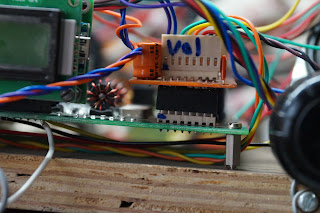
here is some pictures and all details to connect new small pcb to original ver 3 ubitx
Pcb design with sprint layout and will shortly upload all pcb files to FB bitx groups
all original Ideas from Om Farhanji and Mr Lee(KD8CEC), I just design pcb to use it
Tkanks to both
Results
popfix working fine no click from speaker
S-meter sensor circuit working fine ,s-meter tune with ubitx manager ver 1.081
my setup sample value are as 125 128 130 134 140 158 188 223
its very simple to apply this pcb to main ubitx pcb,
1 just remove 12v vcc from pin2of tda2822 audio amplifire
2 remove R70 10E smd register and connect M2(pin6 of p3from new pcb) to R70 relay side pad
as shown in picture below,green wire M2 pin6 from P3
3 connect pin1(Gnd) ,pin3(+12v) and pin5(T/R) to main pcn Radiono 16pin connector as shown
in below picture
4 connect pin4(S-meter out) and pin2 (+5v) to8pin Radiano digital control connector as below
5 Now just remove 8pin front analog connector and fix new pcb P1 in place of it, and fix your
front analog 8pin connector with wira to P2 of new PCB as below
https://youtu.be/CMjlKDSqCYU
I have ubitX ver3 working well with SSB and Digital mods
Just now om Farhan released ver 4 circuit with new transistorised audio amplifire and Tx popfix
circuit,and mods in Rf PA,
I decided to apply audio amp and popfix mod to my ver 3 pcb,and also want to upgrade software
ver 1.08 wirh S-meter and 4line LCD display by KD8CEC
So decided to design pcb for this 3 modifications in one,which is easy to fix on ver 3 pcb
here is some pictures and all details to connect new small pcb to original ver 3 ubitx
Pcb design with sprint layout and will shortly upload all pcb files to FB bitx groups
all original Ideas from Om Farhanji and Mr Lee(KD8CEC), I just design pcb to use it
Tkanks to both
Results
popfix working fine no click from speaker
S-meter sensor circuit working fine ,s-meter tune with ubitx manager ver 1.081
my setup sample value are as 125 128 130 134 140 158 188 223
1 just remove 12v vcc from pin2of tda2822 audio amplifire
2 remove R70 10E smd register and connect M2(pin6 of p3from new pcb) to R70 relay side pad
as shown in picture below,green wire M2 pin6 from P3
in below picture
4 connect pin4(S-meter out) and pin2 (+5v) to8pin Radiano digital control connector as below
5 Now just remove 8pin front analog connector and fix new pcb P1 in place of it, and fix your
front analog 8pin connector with wira to P2 of new PCB as below
Video on how to connect new pcb on ubitx main pcb is available on my youtube channel
https://youtu.be/CMjlKDSqCYU


Is this being offered as a kit a person can purchase?? I would really like to do this modification since it doesn't require surface mount components. 73 Juddie WD8WV
ReplyDeleteno kits is avalable ,pcb design is simple to made it at home with tonner transfer ,73 vu2kyz
DeleteI can put the s meter in a display of two lines?
ReplyDeleteThanks Leo PY1CC.
I can put the s meter in a display of two lines?
ReplyDeleteThanks Leo PY1CC.
yes downloas cec 2 line lcd firmware
ReplyDeletehttp://www.hamskey.com/2018/05/ubitx-firmware-cec-version-108-release.html